CAGE Code : 8AUG0
Duns# : 109436681
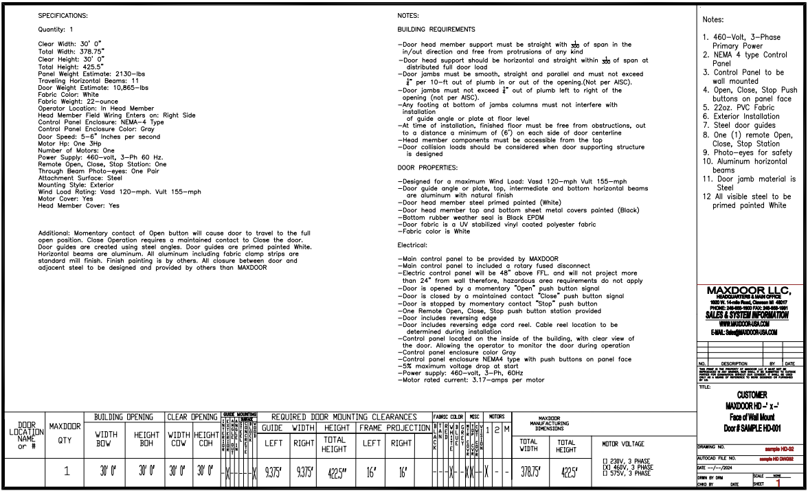
Heavy Duty Vertical Lifting Fabric Door
SPECIFICATION FOR MODEL HD VERTICAL LIFTING FABRIC DOORS
PART 1: GENERAL
It is the intent of this specification to identify design requirements and minimum standards for the quality, construction, delivery, installation, and operation of the vertical lifting fabric door. Minor variations, in accordance with standard practice, shall be indicated on shop drawings and submitted for approval.
1.1 CODES AND STANDARDS:
The following standards form a part of this specification to the extent referenced. References in the body of this specification are by basic designation only.
1.1.1 American Society for Testing and Materials (ASTM)
1.1.2 National Electrical Manufacturer’s Association (NEMA)
1.1.3 Underwriters Laboratories, Inc. (UL)
1.2 QUALITY ASSURANCE
1.2.1 The material, construction, and operation of the door shall conform to the performance specifications contained herein. Approved manufacturer is:
MAXDoor, LLC.
1020 W. 14 Mile Rd.
Clawson, MI 48017-1408
Phone: (248) 915 5838
1.2.2 Manufacturer shall warrant mechanical and electrical components against defects in materials and workmanship for one year beginning from the delivered date.
1.2.3 Each vertical lifting fabric door shall be furnished as a complete unit produced by one manufacturer, including hardware, accessories, and mounting components.
1.3 MANUFACTURING AND INSTALLER QUALIFICATIONS:
1.3.1 The vertical lifting fabric doors shall be the product of a manufacturer who has had at least ten years experience in design, fabrication, erection, and service, and who is regularly engaged in the manufacture of the type of door specified herein. Only manufacturers who can submit evi¬dence of actual installations of comparable design and construction, and that the products have proven practical, durable, and require a minimum of maintenance, will be qualified under this specification.
1.3.2 Installation of the doors shall be by an authorized representative of the door manufacturer and shall be in accordance with approved installation drawings. Mechanics shall be skilled and experienced in the erection of doors of the type specified herein.
1.4 DESIGN REQUIREMENTS:
1.4.1 Door Design: The manufacturer shall design the door in accordance with the criteria specified herein. Doors shall operate properly without binding, interference, or damage to the adjacent structure.
1.4.2 Wind Load: Doors shall be designed to withstand a minimum wind pressure of 20 psf acting alternately inward and outward. Higher wind load ratings are available. Contact the manufacturer with the door size for available higher wind loads.
1.4.3 Door Speed: Single speed doors operate at 6-12 inches per second when opening or closing. Custom High-Speed doors are available. Contact the manufacturer for your specific application.
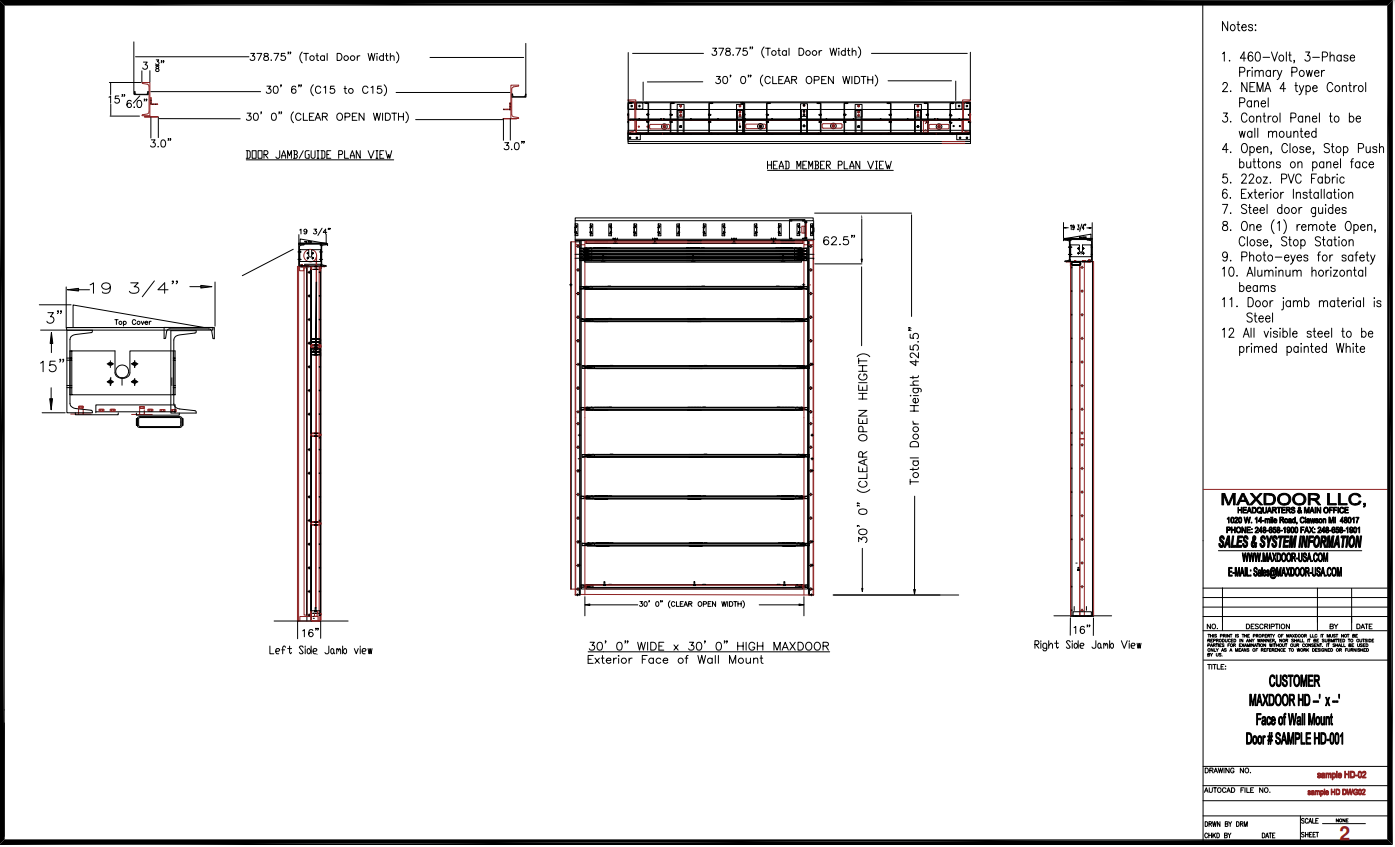
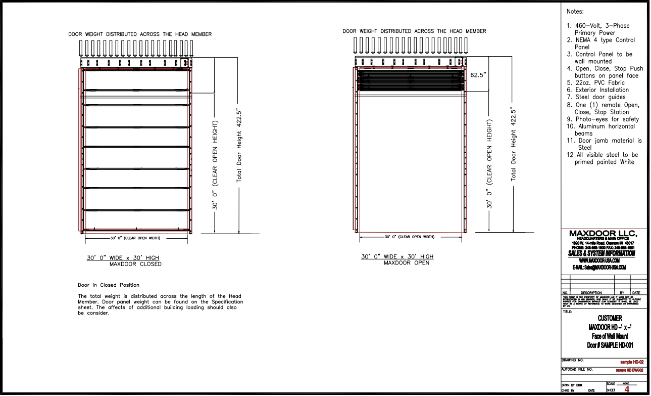
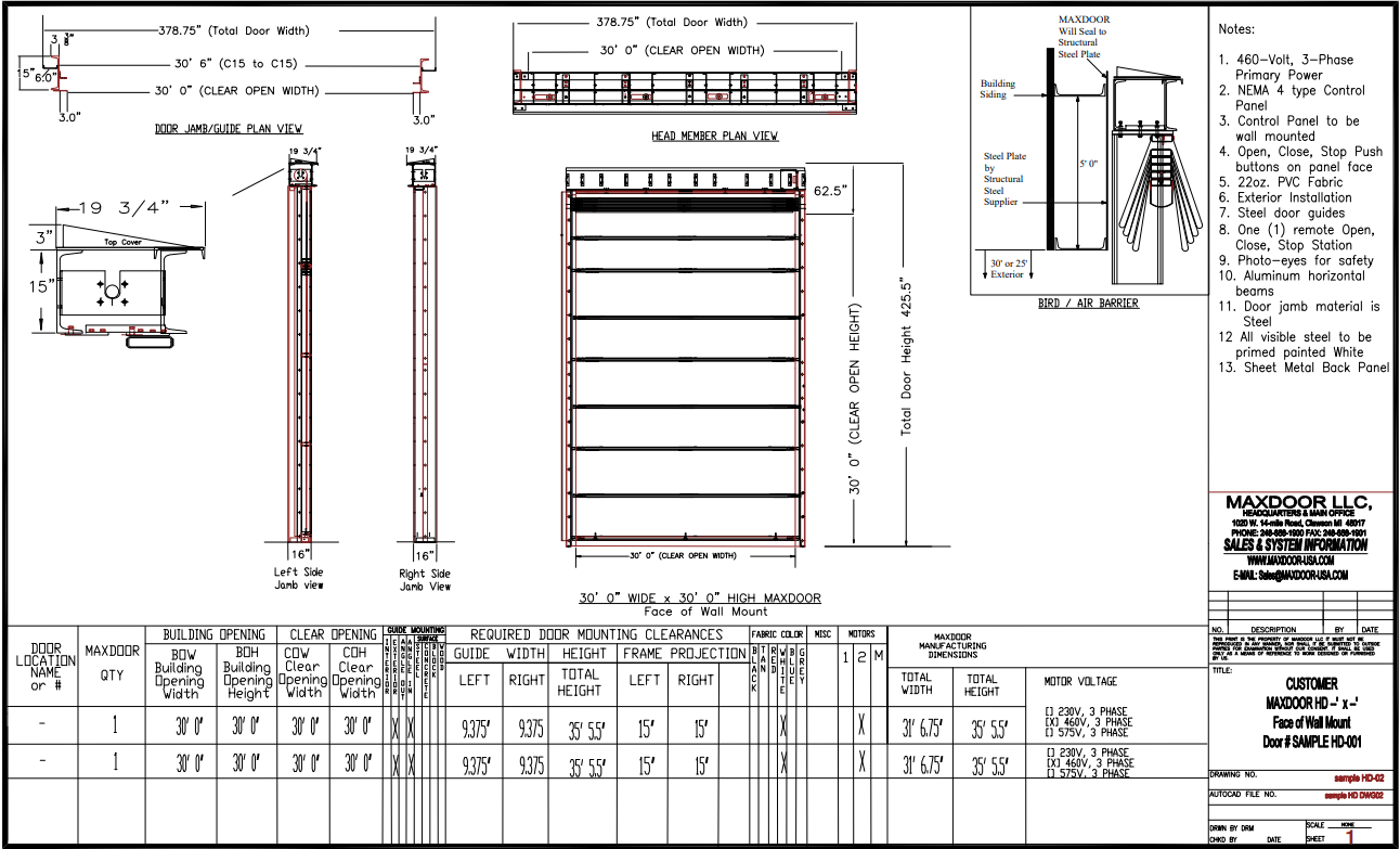
1.4.4 Door Weight: The overhead support structure should be designed for a load of 100 lb./ft. width.
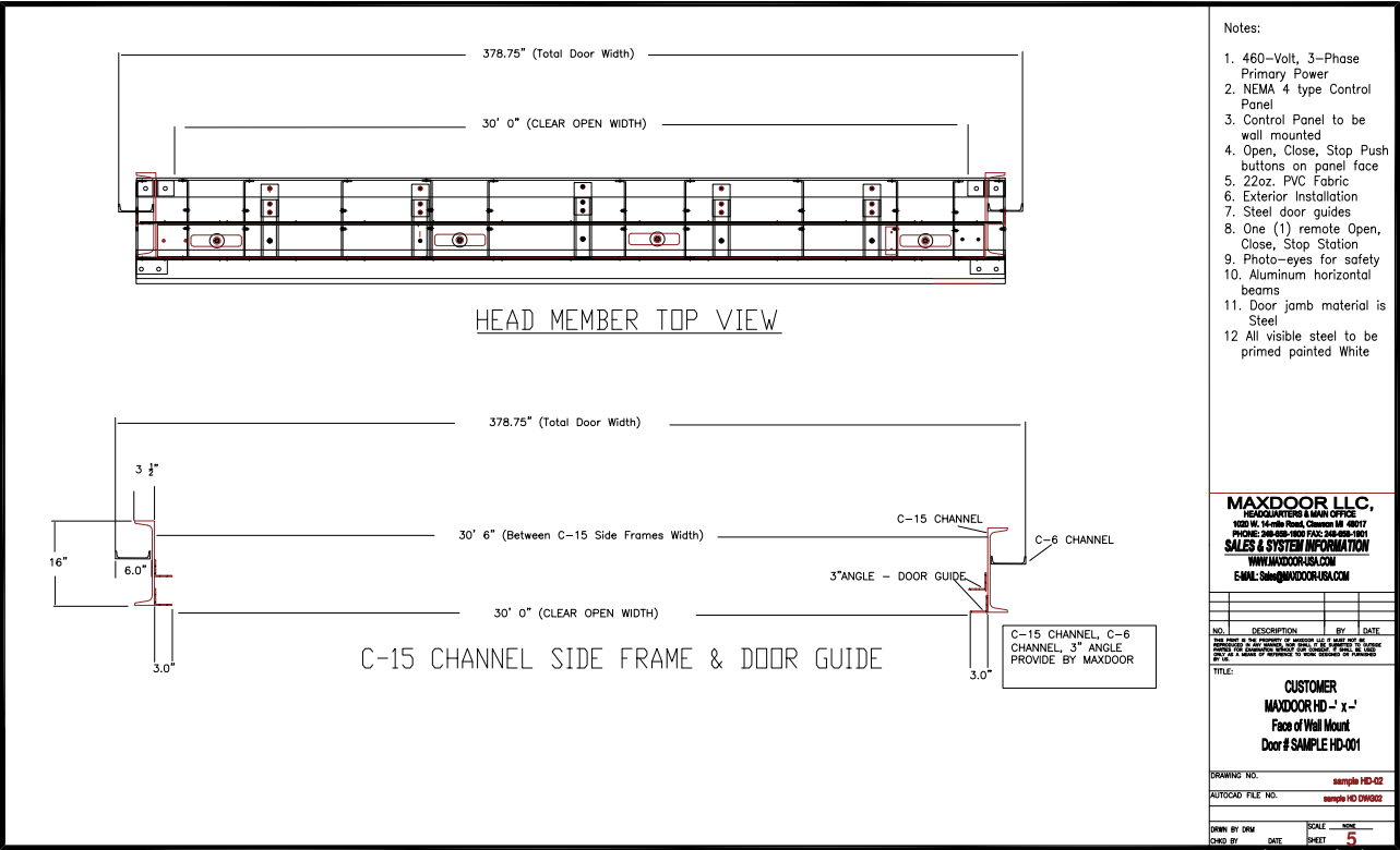
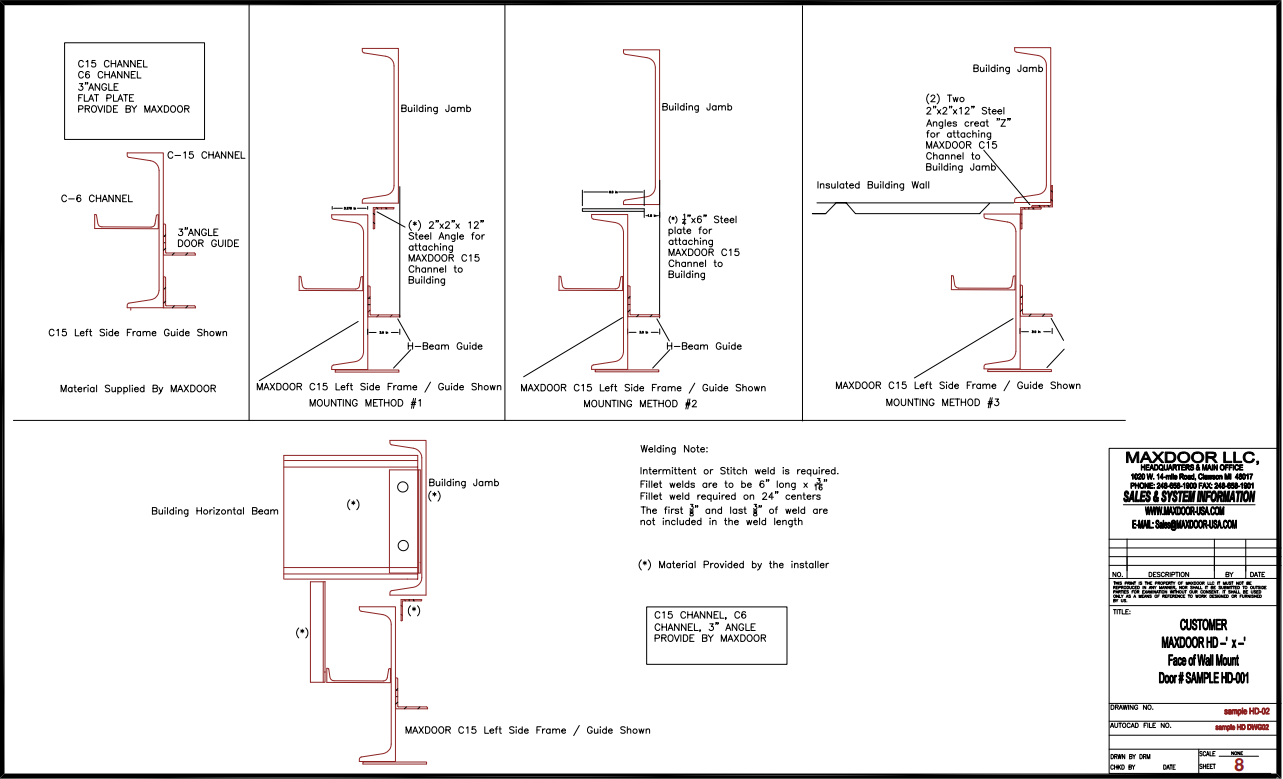
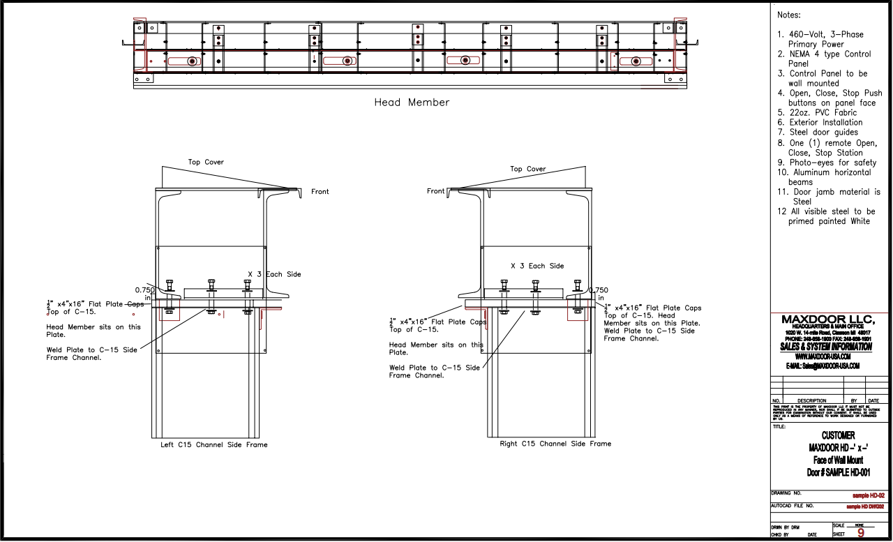
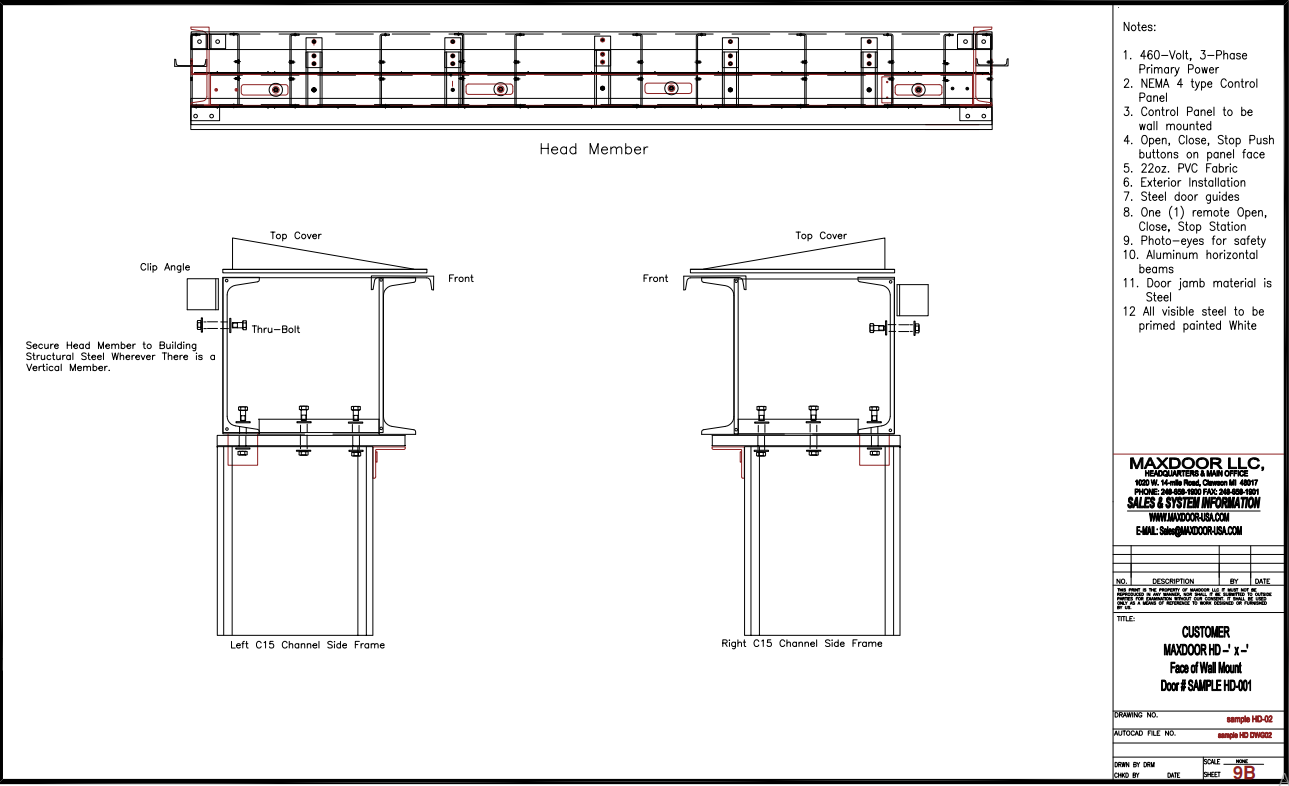
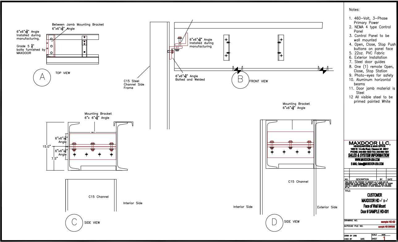
1.4.5 Head-member and Side Frame/Guides: The door is to be provided with a Low-profile Head Member that utilizes twin C15x33.9 Channel as the Front and Rear Members of the Head Member. The Head Member structural steel frame is to be within the design of the Head Member and not an external component. Attaching to External or Overhead I-beams is not allowed. The door is to be provided with C15x33.9 steel channel side frames. The Side Frames shall be cut to size, straightened, have the door guides installed and shipped ready to install. The side frames utilize a full length C6x9 Steel Channel as a stiffener to the C15 Side Frames. The Door Guides are fabricated from Aluminum Angles that are bolted to the C15 Side Frames. Door Guide must be 2 Sections and Front and Rear that can be easily removed for service and maintenance. Door Guides are shipped pre-installed onto Door Side Frames. All Door Frames are primed painted Black.
1.5 SUBMITTALS:
1.5.1 Product Data: Submit manufacturer’s product data, roughing in diagrams for head and jambs, and installation instructions for door unit.
1.5.2 Shop drawings: Submit shop drawings for special com¬ponents which are not fully detailed on the manufacturer’s data sheets.
1.5.3 Samples: Submit color samples of panel fabric for approval. Standard Colors are: White, Black, Tan, Blue, Gray, Red, Brown, Yellow, and Green
1.5.4 Operating Drawings and Instructions: Furnish the follow¬ing at the completion of the installation:
1.5.4.1 Data and/or shop drawings and wiring schematics for doors.
1.5.4.2 Complete manufacturer’s manuals containing instructions for operation and maintenance of doors.
1.6 DELIVERY AND STORAGE:
1.6.1 Supplier shall provide shipment of all materials in the manufacturer’s protective packaging to the job site. Delivery of materials shall be in original rolls, packages, boxes, or crates bearing the manufacturer’s name, brand, model number, and installation location.
1.6.2 The general contractor is responsible for receiving, unloading, and storage of materials. Storage shall be in dry locations with adequate ventilation, free from dust and water, and available for inspection and handling. Handle doors carefully to prevent damage. Remove damaged items that cannot be restored to like-new condition and replace them with new items.
PART 2: PRODUCT
2.1 DOORS:
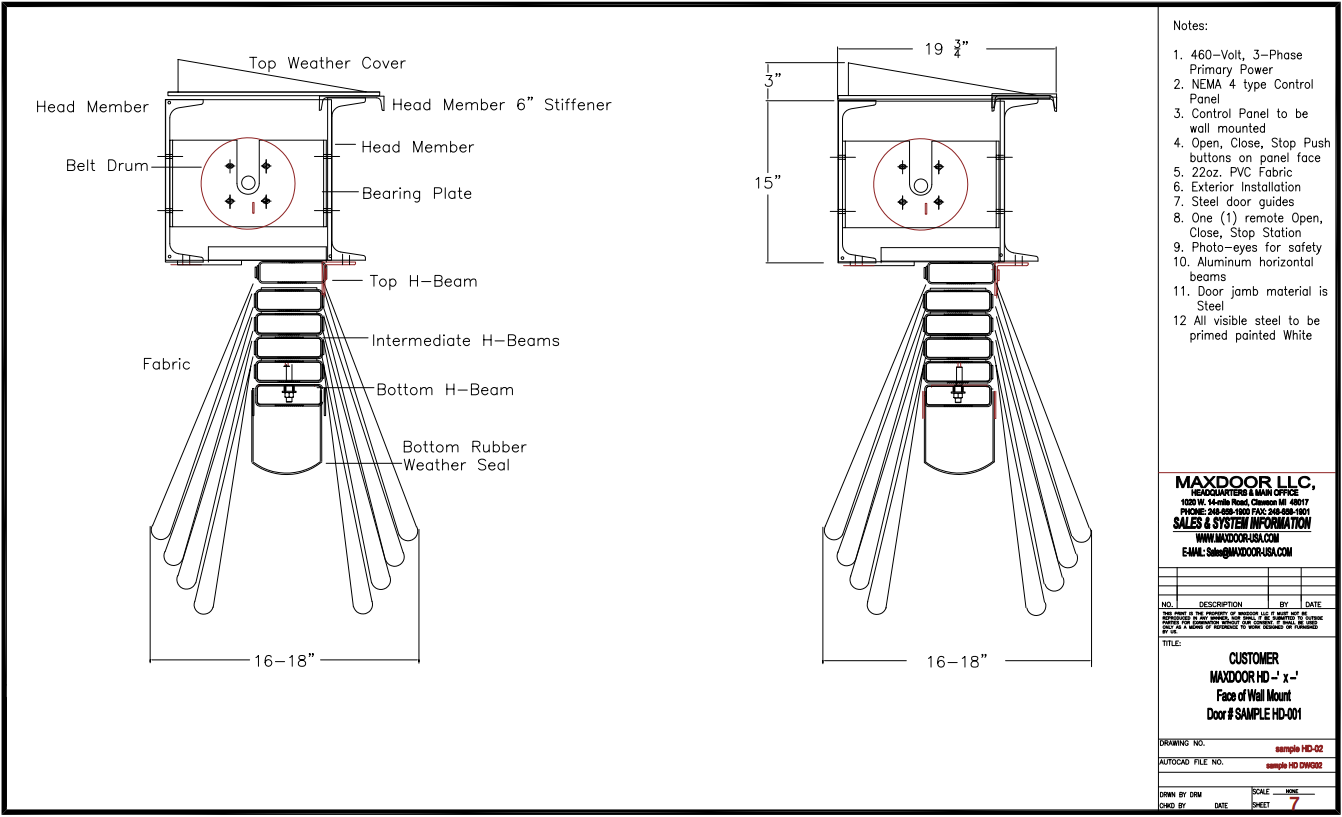
2.1.1 Door fabric: The fabric panel shall cover both sides of the door. The fabric shall be a heavy-duty vinyl coated fabric weighing approximately 22 ounces per square yard, capable of carrying 250 pounds per inch per panel. It shall be UV stabilized and suitable to withstand temperatures between -38 to +158 degrees F. The fabric shall be attached to both sides of the intermediate beams, top beam, and bottom beam.
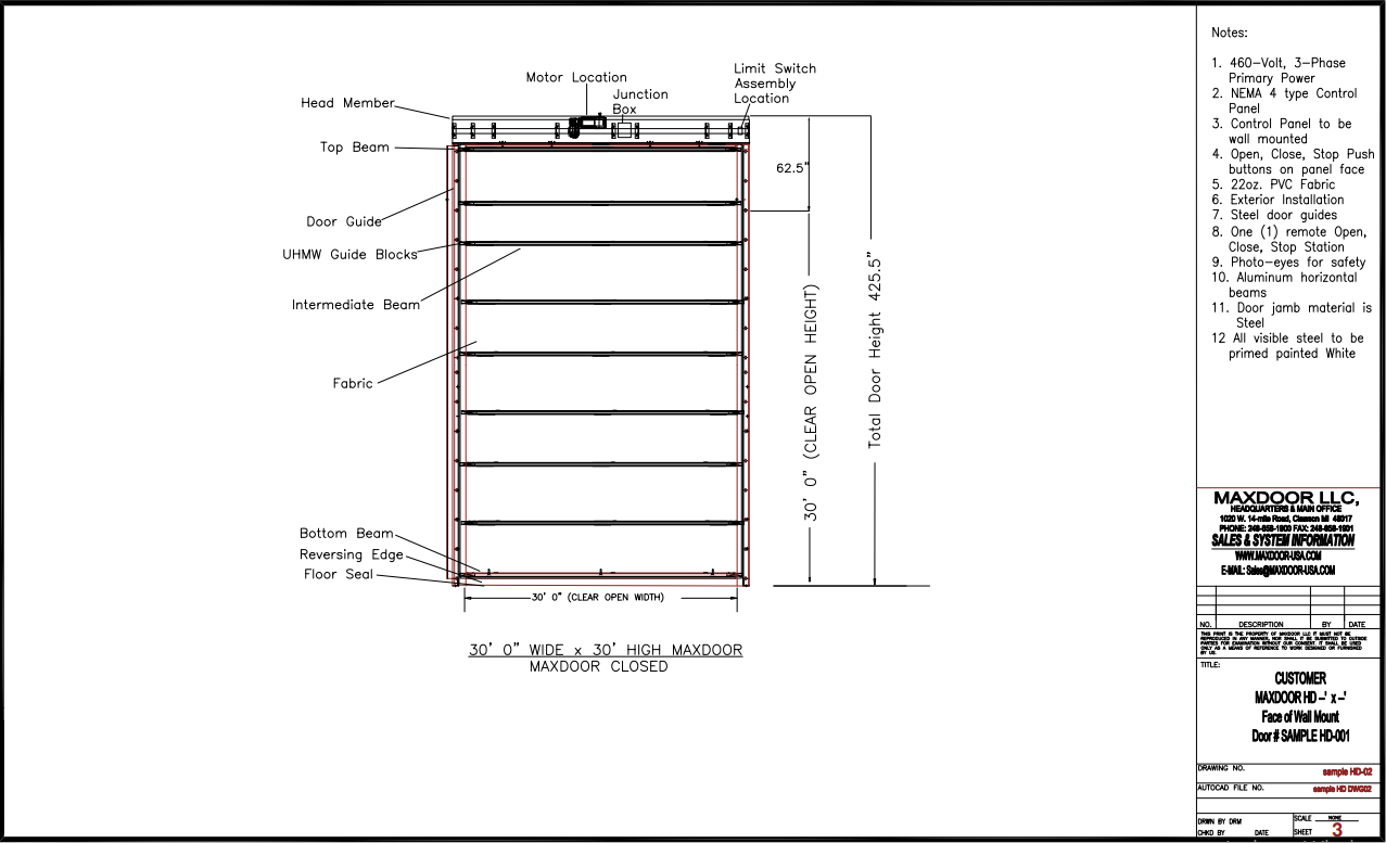
2.1.2 Door Beams: The intermediate beams shall be a rectangle aluminum tube profile with a load capacity dependent on the door width. Rectangle Aluminum tube will be used on all horizontal beams to minimize torsional twist. The beams shall be spaced 24-48 inches apart. At the end of each beam there shall be a self-lubricating UHMW guide block. Each Beam will have several machined oval shaped cut outs that allow the Lifting Belts to travel through the center of the horizontal beams.
2.1.3 Door Side Frame: The face of wall mount structural steel Door Side Frames shall be an integral part of the door, made of steel Channel or Rectangle Tube. The structural steel Side Frames are fabricated and shipped with the door guides being totally pre-assembled. For Between jamb mounting the door guides will mount to the building structural steel. The Door Guides are bolted to the side frame or building steel and have weather sealing surfaces on the inside and the outside faces. No springs, counterweights, or mechanical latching devices shall be located inside the guides. The Door Guides shall be free of any device that could be damaged in case of collision. The Door Guides will be two Aluminum Angles having a front and rear. The front and rear sections will be independent and removable for easy maintenance, All Side Frame steel is pre-finished with a Black primer paint. Aluminum Guides shall have a factory mill finished.
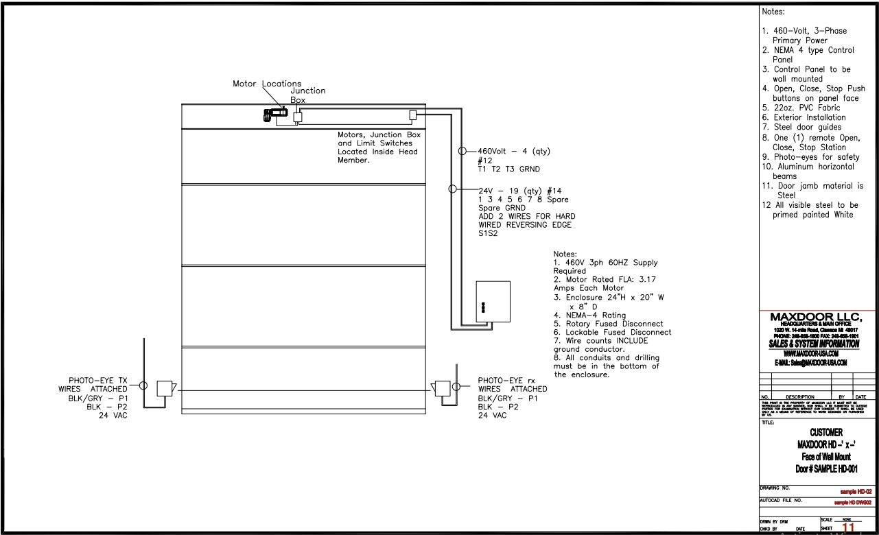
2.1.4 Head Member: The Head Member will be pre-assembled. Gear-motor with Brake, Door Panel, Lifting Belts, Main Shaft, Limit Switches are shipped installed and ready for installation. The Head Member construction will utilize twin C-15 Channel beams as an internal integral part of the head member. A C6 x 9 channel will cap the front C15 x 33.9 Channel. All Steel will be internal to the head member. The door head member shall be completely pre-assembled. The drive mechanism shall consist of a single main shaft, lifting belts, belt drums and motor. The gear motor shall be of a reduction type with brake designed for high cycle operation. A manual brake release and means of manual operation shall be fitted to the gear motor. The gear motor shall be removable without disturbing limit switch adjustment. No springs shall be used to facilitate door movement. All exposed components of the header member shall be factory primed painted black.
2.1.5A Lifting System: The belts run through the top and intermediate horizontal beams. The belts are attached to the bottom beam of the door leaf. Belt guide rollers located on the top beam, keep the lifting belts centered.
2.1.5B Lifting System: One or Two parallel shaft Gear-motor with brake are used. Gear Motors are located inside the head member. Motor size is determined by door size and required operating speed. Single motor operator is located in the Center of the Head Member. Multiple motor systems are synchronized through the motor controller or connection to main shaft.
2.1.5.C Lifting System: Main Shaft connects directly to Gear Motor through parallel shaft gearbox. Multiple Lifting Belt Drums, (Minimum of 4 Belt Drums) are located on the Main Shaft. One belt drum per lifting belt. Main Shaft flange bearings have grease fittings for easy maintenance.
2.1.5.D Lifting System: Direct Drive Gear Motor with Brake on the main shaft.
2.1.6 Lifting Belts: Each door shall be supplied with a minimum of four Lifting Belts. The Lifting Belts are spaced across the width of the door. There are no Lifting Belts inside the door guides. Single Lifting Belt with mechanical drop devices are not allowed. The Lifting Belts will also help minimize how far the curtain can blow in between the horizontal beams when the door is closed. The Lifting Belts shall be position so that they are free to travel with the Curtain Bundle should there be a collision and the Horizontal beams get knocked out the door guides.
2.1.7A Over Travel Switch: An Over Travel Limit Switch monitors the door upward travel and will cut the power to the drive unit should the door over travel.
2.1.8 Bottom Beam: The Bottom Horizontal Beam will be the same size and material as all other horizontal beams. A U-shaped EPDM rubber seal shall be provided to form a tight seal between the bottom of the door the grade surface, even on uneven surfaces. The door bottom beam shall include an extrusion for attachment of a reversing edge.
2.1.9 Reversing Edge: An optional Reversing Edge is available on all doors with maintained contact close push button operation. Reversing Edge is standard on all other doors. The bottom of the door will be equipped with a safety edge to automatically stop the door should it contact any obstruction when traveling in the downward position. The safety edge shall be wired normally closed so that it continuously monitors its own circuit for failure.
2.1.10 Weather Seals: The vertical sides of the door panel will be sealed by the curtain material overlapping the door guides. The Interior and Exterior sides of the Door Panel will overlap the door guides. The weather seal surface will be 1- 2” wide by the door height.
The bottom of the door will seal via a “U” shaped EPDM Rubber Seal. The top of the door is to be sealed between the head member and the building wall material.
2.1.11A Control Panel: The door manufacturer shall supply a pre-wired control panel to control door operation. The control panel shall contain interlocks to preclude personnel injury, including a Maintenance mode manual selector switch located at the Junction box in the Head Member. The Maintenance Switch will not allow the door to operate should any Open or Close push buttons or Sensors be activated. The Maintenance Switch will be turned off whenever the motor is manually rotated. An interlock switch is installed between the power supply system and use of the manual hand chain when used for manual operation. The panel enclosure shall be NEMA-4 rated. Internal wiring shall be per UL. Panels shall include Open, Close and Stop push button controls, cycle counter, Lockable Flange Mount Fused Disconnect, 24-VDC Power Supply, Terminal Strip for Field Wiring termination, Motor Over-Load, Reversing Contactors.
2.1.11B Control Panel: The control panel will utilize a PLC (Programmable Logic Controller. Door positioning will be controlled by a Limit Switch Assemble.
2.1.12 Protection Features: Fuses shall be utilized to protect the system from power line overcurrent and from secondary control voltage overcurrent. Additionally, a system shall be provided to detect overcurrent to the motor.
2.1.13 Motor Cover: A metal weather cover for the motor cover is standard on all doors.
2.1.14 Additional Features: The door can be provided with the following optional features:
- Remote Open, Close, Stop station
- Long distance Radio Controls
- Reversing Edge Cord Reel
- Photocell, Motion, Presence, Induction Loop, Laser Sensors
- Emergency power connection to the control panel
- Explosion proof environment components
- High Speed Operation
- Insulated Fabric Curtain
- Custom control panels
2.2 OPERATION:
2.2.1 Door operation: The vertical lifting fabric door shall guide up and down in the weather sealing vertical guides attached to the Side Frames. The door shall operate by lifting the bottom beam upwards, thereby stacking the interme¬diate beams one on top of the other, with the fabric panel folding in pleats. The fabric panel shall go over the top beam, covering both sides of the door, and shall be attached to the intermediate beams batten strips with mechanical fastener. When the door is fully closed, the intermediate beams shall hang between the two fabric door panels thus pulling the fabric tight. The tension created in the fabric panels shall stabilize the intermediate beams. When the door is fully closed the Lift belts will become slack but still limit how much the fabric can blow in between the horizontal beams.
2.2.2 Electrical Operation: When the door is opened complete¬ly it shall stop on the primary top limit switch. In case of overtravel, a secondary limit switch shall stop the door to prevent damage. The over travel limit switch shall be acti¬vated by the uppermost traveling intermediate beam. The drive unit shall be stopped by the Closed Limit Switch when the door is fully closed. The door operation shall be con¬trolled by three pushbuttons marked “Open”, “Close”, and “Stop”. The door manufacturer shall provide a NEMA approved enclosure which is factory wired and equipped with instantaneous overload relay.
PART 3: EXECUTION
3.1 INSTALLATION
3.1.1 Building Power: If permanent electrical power is not avail¬able when the door is being installed, the General Contractor shall make provision for and obtain a tempo¬rary source of electrical power to allow the door installer to install, test, and adjust the door under power.
3.1.2 Assembly: Assemble and install the doors and acces¬sories in accordance with the manufacturer’s recommen¬dations and installation manual. Secure Side Frames to walls plum, level, and in line. Anchor Side Frames at spacing indicat¬ed on installation drawings. The Installer is to provide any additional supports as necessary for attachment of Side Frames to the building. There should be a support brace wherever there is a building horizontal beam going up the height of the door. The Head Member should be attached to the building at several locations going across the width of the door opening.
3.1.3 Cleaning: Clean doors after erection on both interior and exterior. Touch up prime painted Side Frames were welding or grinding has occurred. All Finish Painting is by others.
3.1.4 Testing: Upon completion of installation, including work by other trades, lubricate, adjust, and test doors to verify operation in accordance with manufacturer’s product data sheet. Complete signed installation form and send to MAXDOOR.